- Authors

- Name
- Youngju Kim
- @fjvbn20031
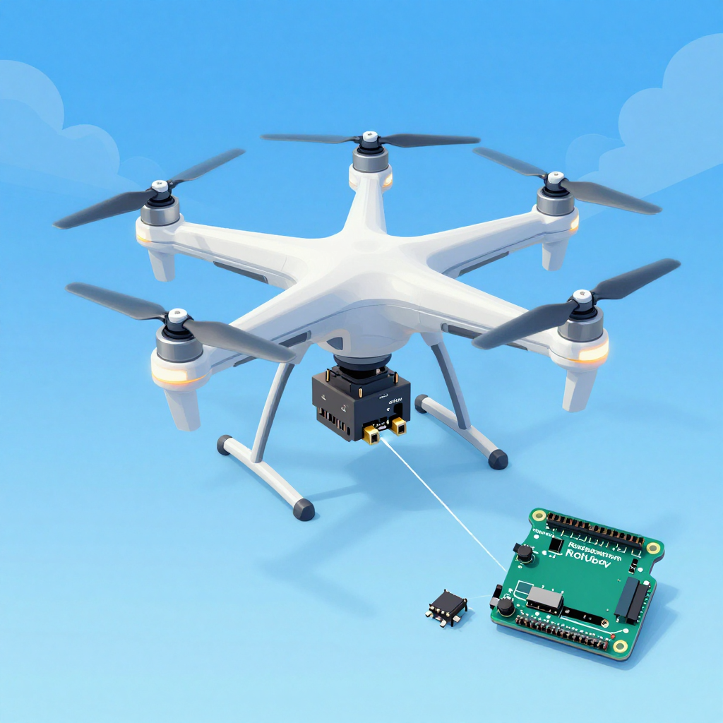
本文是这个系列的枢纽文章。如果想一次性理解传感器、控制器、视觉处理直到自主飞行的完整系统,从这里开始就对了。如果你更关注小型化的 BLE 传感器节点、低功耗设计、TinyML 边缘设备,接下来读 Seeed Studio XIAO nRF52840 完全指南 — BLE IoT 项目实战 更合适。
引言
购买一台无人机直接飞和亲手打造后再飞,完全是两种不同的体验。从硬件组装、PID 控制调参、传感器融合,到自主飞行算法 — 这是一个把控制工程的方方面面都浓缩在一起的项目。
Part 1: 硬件配置
四旋翼零件清单
必需组件:
├── 机架: F450(对角450mm,入门首选)              ~₩15,000
├── 电机: 2212 920KV BLDC × 4                      ~₩24,000
├── ESC: SimonK 30A × 4(电子调速器)              ~₩20,000
├── 螺旋桨: 1045(10英寸)× 4(CW 2 + CCW 2)      ~₩5,000
├── 电池: 3S 11.1V 2200mAh LiPo                    ~₩20,000
├── 控制器: Arduino Mega 2560 或 STM32              ~₩15,000
├── IMU传感器: MPU6050(加速度计+陀螺仪)          ~₩3,000
├── 气压计: BMP280(定高保持)                      ~₩3,000
├── GPS: Neo-6M(自主飞行用)                       ~₩10,000
├── 接收机: FlySky FS-iA6B(含遥控器)              ~₩30,000
└── 电源分配板(PDB)+ 连接器                        ~₩5,000
总计: ~₩150,000(DJI Mini 4价格的1/5!)

可选组件:
├── Raspberry Pi 4(视觉处理、自主飞行)            ~₩60,000
├── Pi Camera V2(目标追踪)                        ~₩30,000
├── 超声波传感器: HC-SR04(低空测距)               ~₩2,000
├── 光流传感器: PMW3901(室内定位保持)             ~₩15,000
└── Telemetry: HC-12 433MHz(地面监控)             ~₩5,000
电机布局
       Front
    M1(CW)  M2(CCW)
      \      /
       \    /
        \  /
     [FC Board]
        /  \
       /    \
      /      \
    M3(CCW) M4(CW)
       Back

CW = 顺时针,CCW = 逆时针
对角电机沿同一方向旋转!
→ 通过扭矩抵消实现机体稳定
接线图
电池(3S LiPo 11.1V)
  │
  ├──[PDB]── ESC1 ── M1
  │          ESC2 ── M2
  │          ESC3 ── M3
  │          ESC4 ── M4
  │
  ├──[BEC 5V]── Arduino Mega
  │               ├── MPU6050(I2C: SDA→D20, SCL→D21)
  │               ├── BMP280(I2C: 同一总线)
  │               ├── GPS Neo-6M(Serial2: TX→D16, RX→D17)
  │               ├── 接收机(PPM→D2 或各通道)
  │               └── ESC信号(D3, D5, D6, D9)
  │
  └──[5V]── Raspberry Pi 4(USB连接或Serial)
              └── Pi Camera
Part 2: PID控制 — 无人机的核心
什么是PID?
目标: 希望让无人机保持水平(Roll = 0°)

当前状态: Roll = 5°(向右倾斜)
误差(Error)= 目标 - 当前 = 0° - 5° = -5°

PID输出 = P + I + D

P(比例): 按误差比例进行修正
  → -5° × Kp = 即时响应,但可能产生振荡

I(积分): 修正误差的累积
  → 消除微小偏差,但过大会导致超调

D(微分): 修正误差的变化率
  → 抑制急剧变化,防止振荡
Arduino PID实现
// PID控制器类
class PIDController {
private:
    float Kp, Ki, Kd;
    float prevError = 0;
    float integral = 0;
    float maxIntegral = 300;  // 防止积分饱和
    unsigned long prevTime = 0;

public:
    PIDController(float p, float i, float d)
        : Kp(p), Ki(i), Kd(d) {}

    float compute(float setpoint, float measured) {
        unsigned long now = micros();
        float dt = (now - prevTime) / 1000000.0f;  // 单位:秒
        if (dt <= 0 || dt > 0.5) dt = 0.004;  // 安全保护
        prevTime = now;

        float error = setpoint - measured;

        // P: 比例
        float P = Kp * error;

        // I: 积分(防止饱和)
        integral += error * dt;
        integral = constrain(integral, -maxIntegral, maxIntegral);
        float I = Ki * integral;

        // D: 微分(基于测量值 — 防止setpoint变化时的突跳)
        float derivative = (error - prevError) / dt;
        float D = Kd * derivative;
        prevError = error;

        return P + I + D;
    }

    void reset() {
        prevError = 0;
        integral = 0;
    }
};

// Roll、Pitch、Yaw 各自使用独立的PID
PIDController rollPID(1.2, 0.04, 18.0);
PIDController pitchPID(1.2, 0.04, 18.0);
PIDController yawPID(3.0, 0.02, 0.0);
传感器融合(互补滤波器)
#include <Wire.h>
#include <MPU6050.h>

MPU6050 mpu;

float roll = 0, pitch = 0, yaw = 0;
const float ALPHA = 0.98;  // 互补滤波系数

void updateIMU() {
    int16_t ax, ay, az, gx, gy, gz;
    mpu.getMotion6(&ax, &ay, &az, &gx, &gy, &gz);

    // 加速度计 → 绝对角度(较慢但无漂移)
    float accelRoll = atan2(ay, az) * 180.0 / PI;
    float accelPitch = atan2(-ax, sqrt(ay*ay + az*az)) * 180.0 / PI;

    // 陀螺仪 → 角速度积分(较快但存在漂移)
    float dt = 0.004;  // 250Hz
    float gyroRollRate = gx / 131.0;   // °/s
    float gyroPitchRate = gy / 131.0;
    float gyroYawRate = gz / 131.0;

    // 互补滤波:陀螺仪(短期)+ 加速度计(长期)融合
    roll = ALPHA * (roll + gyroRollRate * dt) + (1 - ALPHA) * accelRoll;
    pitch = ALPHA * (pitch + gyroPitchRate * dt) + (1 - ALPHA) * accelPitch;
    yaw += gyroYawRate * dt;  // 仅使用陀螺仪(加速度计无法求出yaw)
}
电机混控
#include <Servo.h>

Servo motor[4];

void setup() {
    motor[0].attach(3);   // 前左(CW)
    motor[1].attach(5);   // 前右(CCW)
    motor[2].attach(6);   // 后左(CCW)
    motor[3].attach(9);   // 后右(CW)

    // ESC初始化(1000~2000μs PWM)
    for (int i = 0; i < 4; i++) {
        motor[i].writeMicroseconds(1000);
    }
    delay(2000);
}

void setMotors(float throttle, float rollOut, float pitchOut, float yawOut) {
    // 电机混控公式
    float m1 = throttle + pitchOut + rollOut - yawOut;  // 前左 CW
    float m2 = throttle + pitchOut - rollOut + yawOut;  // 前右 CCW
    float m3 = throttle - pitchOut + rollOut + yawOut;  // 后左 CCW
    float m4 = throttle - pitchOut - rollOut - yawOut;  // 后右 CW

    // 范围限制(1000~2000μs)
    motor[0].writeMicroseconds(constrain(m1, 1100, 1900));
    motor[1].writeMicroseconds(constrain(m2, 1100, 1900));
    motor[2].writeMicroseconds(constrain(m3, 1100, 1900));
    motor[3].writeMicroseconds(constrain(m4, 1100, 1900));
}
主循环(250Hz)
void loop() {
    // 1. 读取传感器
    updateIMU();

    // 2. 读取遥控器输入
    float targetRoll = map(rcChannel[0], 1000, 2000, -30, 30);
    float targetPitch = map(rcChannel[1], 1000, 2000, -30, 30);
    float targetYaw = map(rcChannel[3], 1000, 2000, -180, 180);
    float throttle = rcChannel[2];

    // 3. PID计算
    float rollOut = rollPID.compute(targetRoll, roll);
    float pitchOut = pitchPID.compute(targetPitch, pitch);
    float yawOut = yawPID.compute(targetYaw, yaw);

    // 4. 电机输出
    if (throttle > 1100) {  // 安全: 仅当油门超过最小值时
        setMotors(throttle, rollOut, pitchOut, yawOut);
    } else {
        for (int i = 0; i < 4; i++)
            motor[i].writeMicroseconds(1000);  // 电机停止
    }

    // 保持250Hz
    while (micros() - loopTimer < 4000);
    loopTimer = micros();
}
Part 3: Raspberry Pi 视觉控制
# 在Raspberry Pi上进行目标追踪 + 向Arduino发送指令
import cv2
import serial
import struct

# 与Arduino的串口通信
arduino = serial.Serial('/dev/ttyACM0', 115200)

# 摄像头
cap = cv2.VideoCapture(0)
cap.set(cv2.CAP_PROP_FRAME_WIDTH, 320)
cap.set(cv2.CAP_PROP_FRAME_HEIGHT, 240)

# 颜色追踪(跟随红色物体)
while True:
    ret, frame = cap.read()
    hsv = cv2.cvtColor(frame, cv2.COLOR_BGR2HSV)

    # 红色掩膜
    mask = cv2.inRange(hsv, (0, 120, 70), (10, 255, 255))
    contours, _ = cv2.findContours(mask, cv2.RETR_EXTERNAL, cv2.CHAIN_APPROX_SIMPLE)

    if contours:
        largest = max(contours, key=cv2.contourArea)
        M = cv2.moments(largest)
        if M["m00"] > 500:
            cx = int(M["m10"] / M["m00"])
            cy = int(M["m01"] / M["m00"])

            # 相对屏幕中心(160,120)的误差
            error_x = cx - 160  # 左右
            error_y = cy - 120  # 上下

            # 向Arduino发送修正指令
            cmd = struct.pack('hh', error_x, error_y)
            arduino.write(cmd)
Part 4: 实战控制系统案例
倒立摆(Inverted Pendulum)
// 倒立摆 = 无人机控制的缩小版
// 让杆保持垂直的问题 = 让无人机保持水平的问题

// 用旋转编码器读取角度
volatile long encoderCount = 0;
float pendulumAngle = 0;

void encoderISR() {
    encoderCount += (digitalRead(ENCODER_B) == HIGH) ? 1 : -1;
}

void setup() {
    attachInterrupt(digitalPinToInterrupt(ENCODER_A), encoderISR, RISING);
}

void loop() {
    pendulumAngle = encoderCount * 360.0 / 2400.0;  // PPR=600, x4

    // 用PID控制电机
    float output = balancePID.compute(0, pendulumAngle);  // 目标:0°
    setMotor(output);
}
循线小车(自主导航基础)
// 用5个IR传感器检测线路
int sensors[5] = {A0, A1, A2, A3, A4};

float getLinePosition() {
    int values[5];
    float weighted = 0, total = 0;
    for (int i = 0; i < 5; i++) {
        values[i] = analogRead(sensors[i]);
        weighted += values[i] * (i - 2) * 1000;  // -2000 ~ +2000
        total += values[i];
    }
    return weighted / total;  // -2000(左) ~ +2000(右)
}

void loop() {
    float position = getLinePosition();  // 当前位置
    float correction = linePID.compute(0, position);  // 目标: 中央(0)

    int leftSpeed = baseSpeed + correction;
    int rightSpeed = baseSpeed - correction;
    setMotors(leftSpeed, rightSpeed);
}
PID调参指南
Ziegler-Nichols方法:
1. 从 Ki = 0、Kd = 0 开始
2. 逐渐增大Kp,找到开始出现振荡的值(Ku)
3. 测量振荡周期(Tu)
4. 计算:
   Kp = 0.6 × Ku
   Ki = 2 × Kp / Tu
   Kd = Kp × Tu / 8

实战技巧:
├── 先只用P: 响应快,稍有振荡也可接受
├── 加入D: 抑制振荡(约为P的10~20倍)
├── 加入I: 消除稳态误差(只加一点!)
└── 无人机中I值过大很危险(积分饱和)
本嵌入式实战系列的下一篇
- Seeed Studio XIAO nRF52840 完全指南 — BLE IoT 项目实战 如果你想做的不是无人机这样的大型控制系统,而是基于BLE的传感器节点、低功耗可穿戴设备、TinyML边缘设备,这篇文章更适合。
📝 测验 — 无人机与控制系统(点击查看!)
Q1. PID中P、I、D各自的作用是什么? ||P(比例):与误差成正比的即时修正。I(积分):消除累积误差(稳态误差)。D(微分):抑制急剧变化(防止振荡)||
Q2. 四旋翼中对角电机沿同一方向旋转的原因是什么? ||扭矩抵消。CW和CCW电机呈对角布置,使整体扭矩为0。若只有同方向的电机,机体就会自转||
Q3. 互补滤波器中ALPHA为0.98意味着什么? ||以陀螺仪(短期、快速)98% + 加速度计(长期、稳定)2%的比例融合。陀螺仪快但会漂移,加速度计慢但能提供绝对值||
Q4. 什么是积分饱和(Integral Windup)? ||电机输出饱和的状态下积分值持续增大的现象。饱和解除时会产生过度超调。用constrain限制积分值来防止||
Q5. ESC的PWM范围1000~2000μs各自代表什么? ||1000μs:电机停止。2000μs:最大转速。1500μs:中间值。ESC接收这个PWM信号来控制BLDC电机的三相电流||