- Authors
- Name
- Introduction
- Part 1: Hardware Configuration
- Part 2: PID Control — The Heart of the Drone
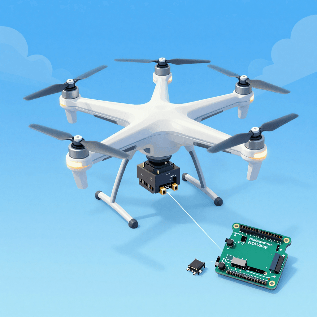
- Part 3: Raspberry Pi Vision Control
- Part 4: Practical Control System Examples
- PID Tuning Guide
Introduction
Buying a drone and flying it is a completely different experience from building one yourself and flying it. Hardware assembly, PID tuning, sensor fusion, autonomous flight algorithms — this project brings together everything in control engineering.
Part 1: Hardware Configuration
Quadcopter Parts List
Essential Components:
├── Frame: F450 (450mm diagonal, ideal for beginners)       ~$12
├── Motors: 2212 920KV BLDC × 4                             ~$18
├── ESC: SimonK 30A × 4 (Electronic Speed Controller)       ~$15
├── Propellers: 1045 (10-inch) × 4 (CW 2 + CCW 2)          ~$4
├── Battery: 3S 11.1V 2200mAh LiPo                          ~$15
├── Controller: Arduino Mega 2560 or STM32                   ~$12
├── IMU Sensor: MPU6050 (Accelerometer + Gyroscope)          ~$3
├── Barometer: BMP280 (Altitude hold)                        ~$3
├── GPS: Neo-6M (For autonomous flight)                      ~$8
├── Receiver: FlySky FS-iA6B (with transmitter)              ~$23
└── Power Distribution Board (PDB) + Connectors              ~$4
Total: ~$117 (1/5 the price of a DJI Mini 4!)

Optional Components:
├── Raspberry Pi 4 (Vision processing, autonomous flight)    ~$45
├── Pi Camera V2 (Object tracking)                           ~$23
├── Ultrasonic Sensor: HC-SR04 (Low altitude measurement)    ~$2
├── Optical Flow Sensor: PMW3901 (Indoor position hold)      ~$12
└── Telemetry: HC-12 433MHz (Ground monitoring)              ~$4
Motor Layout
       Front
    M1(CW)  M2(CCW)
      \      /
       \    /
        \  /
     [FC Board]
        /  \
       /    \
      /      \
    M3(CCW) M4(CW)
       Back

CW = Clockwise, CCW = Counter-Clockwise
Diagonal motors rotate in the same direction!
→ Torque cancellation for airframe stability
Wiring Diagram
Battery (3S LiPo 11.1V)
  │
  ├──[PDB]── ESC1 ── M1
  │          ESC2 ── M2
  │          ESC3 ── M3
  │          ESC4 ── M4
  │
  ├──[BEC 5V]── Arduino Mega
  │               ├── MPU6050 (I2C: SDA→D20, SCL→D21)
  │               ├── BMP280 (I2C: same bus)
  │               ├── GPS Neo-6M (Serial2: TX→D16, RX→D17)
  │               ├── Receiver (PPM→D2 or individual channels)
  │               └── ESC Signal (D3, D5, D6, D9)
  │
  └──[5V]── Raspberry Pi 4 (USB or Serial connection)
              └── Pi Camera
Part 2: PID Control — The Heart of the Drone
What is PID?
Goal: Keep the drone level (Roll = 0°)

Current state: Roll = 5° (tilted to the right)
Error = Setpoint - Current = 0° - 5° = -5°

PID Output = P + I + D

P (Proportional): Correction proportional to the error
  → -5° × Kp = immediate response, but may oscillate

I (Integral): Corrects accumulated error
  → Eliminates steady-state offset, but too much causes overshoot

D (Derivative): Corrects the rate of change of error
  → Suppresses sudden changes, prevents oscillation
Arduino PID Implementation
// PID Controller Class
class PIDController {
private:
    float Kp, Ki, Kd;
    float prevError = 0;
    float integral = 0;
    float maxIntegral = 300;  // Prevent integral windup
    unsigned long prevTime = 0;

public:
    PIDController(float p, float i, float d)
        : Kp(p), Ki(i), Kd(d) {}

    float compute(float setpoint, float measured) {
        unsigned long now = micros();
        float dt = (now - prevTime) / 1000000.0f;  // In seconds
        if (dt <= 0 || dt > 0.5) dt = 0.004;  // Safety fallback
        prevTime = now;

        float error = setpoint - measured;

        // P: Proportional
        float P = Kp * error;

        // I: Integral (with windup prevention)
        integral += error * dt;
        integral = constrain(integral, -maxIntegral, maxIntegral);
        float I = Ki * integral;

        // D: Derivative (based on measurement — prevents kick on setpoint change)
        float derivative = (error - prevError) / dt;
        float D = Kd * derivative;
        prevError = error;

        return P + I + D;
    }

    void reset() {
        prevError = 0;
        integral = 0;
    }
};

// Separate PID for Roll, Pitch, and Yaw
PIDController rollPID(1.2, 0.04, 18.0);
PIDController pitchPID(1.2, 0.04, 18.0);
PIDController yawPID(3.0, 0.02, 0.0);
Sensor Fusion (Complementary Filter)
#include <Wire.h>
#include <MPU6050.h>

MPU6050 mpu;

float roll = 0, pitch = 0, yaw = 0;
const float ALPHA = 0.98;  // Complementary filter coefficient

void updateIMU() {
    int16_t ax, ay, az, gx, gy, gz;
    mpu.getMotion6(&ax, &ay, &az, &gx, &gy, &gz);

    // Accelerometer → Absolute angle (slow but no drift)
    float accelRoll = atan2(ay, az) * 180.0 / PI;
    float accelPitch = atan2(-ax, sqrt(ay*ay + az*az)) * 180.0 / PI;

    // Gyroscope → Angular velocity integration (fast but drifts)
    float dt = 0.004;  // 250Hz
    float gyroRollRate = gx / 131.0;   // °/s
    float gyroPitchRate = gy / 131.0;
    float gyroYawRate = gz / 131.0;

    // Complementary filter: Gyro (short-term) + Accelerometer (long-term) fusion
    roll = ALPHA * (roll + gyroRollRate * dt) + (1 - ALPHA) * accelRoll;
    pitch = ALPHA * (pitch + gyroPitchRate * dt) + (1 - ALPHA) * accelPitch;
    yaw += gyroYawRate * dt;  // Gyro only (yaw cannot be derived from accelerometer)
}
Motor Mixing
#include <Servo.h>

Servo motor[4];

void setup() {
    motor[0].attach(3);   // Front-left (CW)
    motor[1].attach(5);   // Front-right (CCW)
    motor[2].attach(6);   // Rear-left (CCW)
    motor[3].attach(9);   // Rear-right (CW)

    // ESC initialization (1000~2000μs PWM)
    for (int i = 0; i < 4; i++) {
        motor[i].writeMicroseconds(1000);
    }
    delay(2000);
}

void setMotors(float throttle, float rollOut, float pitchOut, float yawOut) {
    // Motor mixing formula
    float m1 = throttle + pitchOut + rollOut - yawOut;  // Front-left CW
    float m2 = throttle + pitchOut - rollOut + yawOut;  // Front-right CCW
    float m3 = throttle - pitchOut + rollOut + yawOut;  // Rear-left CCW
    float m4 = throttle - pitchOut - rollOut - yawOut;  // Rear-right CW

    // Range limiting (1000~2000μs)
    motor[0].writeMicroseconds(constrain(m1, 1100, 1900));
    motor[1].writeMicroseconds(constrain(m2, 1100, 1900));
    motor[2].writeMicroseconds(constrain(m3, 1100, 1900));
    motor[3].writeMicroseconds(constrain(m4, 1100, 1900));
}
Main Loop (250Hz)
void loop() {
    // 1. Read sensors
    updateIMU();

    // 2. Read controller input
    float targetRoll = map(rcChannel[0], 1000, 2000, -30, 30);
    float targetPitch = map(rcChannel[1], 1000, 2000, -30, 30);
    float targetYaw = map(rcChannel[3], 1000, 2000, -180, 180);
    float throttle = rcChannel[2];

    // 3. PID computation
    float rollOut = rollPID.compute(targetRoll, roll);
    float pitchOut = pitchPID.compute(targetPitch, pitch);
    float yawOut = yawPID.compute(targetYaw, yaw);

    // 4. Motor output
    if (throttle > 1100) {  // Safety: only when throttle exceeds minimum
        setMotors(throttle, rollOut, pitchOut, yawOut);
    } else {
        for (int i = 0; i < 4; i++)
            motor[i].writeMicroseconds(1000);  // Stop motors
    }

    // Maintain 250Hz
    while (micros() - loopTimer < 4000);
    loopTimer = micros();
}
Part 3: Raspberry Pi Vision Control
# Object tracking on Raspberry Pi + sending commands to Arduino
import cv2
import serial
import struct

# Serial communication with Arduino
arduino = serial.Serial('/dev/ttyACM0', 115200)

# Camera
cap = cv2.VideoCapture(0)
cap.set(cv2.CAP_PROP_FRAME_WIDTH, 320)
cap.set(cv2.CAP_PROP_FRAME_HEIGHT, 240)

# Color tracking (follow a red object)
while True:
    ret, frame = cap.read()
    hsv = cv2.cvtColor(frame, cv2.COLOR_BGR2HSV)

    # Red color mask
    mask = cv2.inRange(hsv, (0, 120, 70), (10, 255, 255))
    contours, _ = cv2.findContours(mask, cv2.RETR_EXTERNAL, cv2.CHAIN_APPROX_SIMPLE)

    if contours:
        largest = max(contours, key=cv2.contourArea)
        M = cv2.moments(largest)
        if M["m00"] > 500:
            cx = int(M["m10"] / M["m00"])
            cy = int(M["m01"] / M["m00"])

            # Error from screen center (160,120)
            error_x = cx - 160  # Horizontal
            error_y = cy - 120  # Vertical

            # Send correction command to Arduino
            cmd = struct.pack('hh', error_x, error_y)
            arduino.write(cmd)
Part 4: Practical Control System Examples
Inverted Pendulum
// Inverted pendulum = scaled-down version of drone control
// Balancing a rod vertically = keeping a drone level

// Read angle with rotary encoder
volatile long encoderCount = 0;
float pendulumAngle = 0;

void encoderISR() {
    encoderCount += (digitalRead(ENCODER_B) == HIGH) ? 1 : -1;
}

void setup() {
    attachInterrupt(digitalPinToInterrupt(ENCODER_A), encoderISR, RISING);
}

void loop() {
    pendulumAngle = encoderCount * 360.0 / 2400.0;  // PPR=600, x4

    // Motor control with PID
    float output = balancePID.compute(0, pendulumAngle);  // Target: 0°
    setMotor(output);
}
Line Tracer (Autonomous Driving Basics)
// Line detection with 5 IR sensors
int sensors[5] = {A0, A1, A2, A3, A4};

float getLinePosition() {
    int values[5];
    float weighted = 0, total = 0;
    for (int i = 0; i < 5; i++) {
        values[i] = analogRead(sensors[i]);
        weighted += values[i] * (i - 2) * 1000;  // -2000 ~ +2000
        total += values[i];
    }
    return weighted / total;  // -2000(left) ~ +2000(right)
}

void loop() {
    float position = getLinePosition();  // Current position
    float correction = linePID.compute(0, position);  // Target: center (0)

    int leftSpeed = baseSpeed + correction;
    int rightSpeed = baseSpeed - correction;
    setMotors(leftSpeed, rightSpeed);
}
PID Tuning Guide
Ziegler-Nichols Method:
1. Start with Ki = 0, Kd = 0
2. Gradually increase Kp until oscillation begins — find this value (Ku)
3. Measure the oscillation period (Tu)
4. Calculate:
   Kp = 0.6 × Ku
   Ki = 2 × Kp / Tu
   Kd = Kp × Tu / 8

Practical Tips:
├── Start with P only: Fast response, slight oscillation is OK
├── Add D: Dampen oscillation (10~20x of P)
├── Add I: Eliminate steady-state error (keep it small!)
└── For drones, too much I is dangerous (integral windup)
Quiz — Drone & Control Systems (Click to check!)
Q1. What are the roles of P, I, and D in PID? ||P (Proportional): Immediate correction proportional to error. I (Integral): Eliminates accumulated error (steady-state error). D (Derivative): Suppresses sudden changes (prevents oscillation)||
Q2. Why do diagonal motors on a quadcopter rotate in the same direction? ||Torque cancellation. CW and CCW motors are placed diagonally so the total torque is zero. With same-direction motors only, the airframe would spin.||
Q3. What does ALPHA = 0.98 mean in the complementary filter? ||Fusion at 98% gyro (short-term, fast) + 2% accelerometer (long-term, stable). The gyro is fast but drifts; the accelerometer is slow but provides absolute values.||
Q4. What is Integral Windup? ||A phenomenon where the integral value keeps growing while motor output is saturated. Causes excessive overshoot when saturation is released. Prevented by constraining the integral value.||
Q5. What do 1000~2000μs mean in the ESC PWM range? ||1000μs: Motor stop. 2000μs: Maximum rotation. 1500μs: Mid-range. The ESC receives this PWM signal and controls the 3-phase current of the BLDC motor.||