- Authors
- Name
- Introduction
- Why Developers Should Learn Electronics
- Roadmap
- What You Need (Under $40 is enough!)
- Fundamental Concepts: Just 3 Things
- Exercise 1: Blinking an LED (Hello World)
- Exercise 2: Control LED with a Button
- Exercise 3: Temperature & Humidity Sensor (DHT11)
- Exercise 4: Servo Motor Control (The Start of a Table Tennis Robot!)
- Exercise 5: LED Brightness Control with PWM
- Developer Project Ideas
- AI + Electronics Fusion (Ultimate Goal)
- Series Roadmap
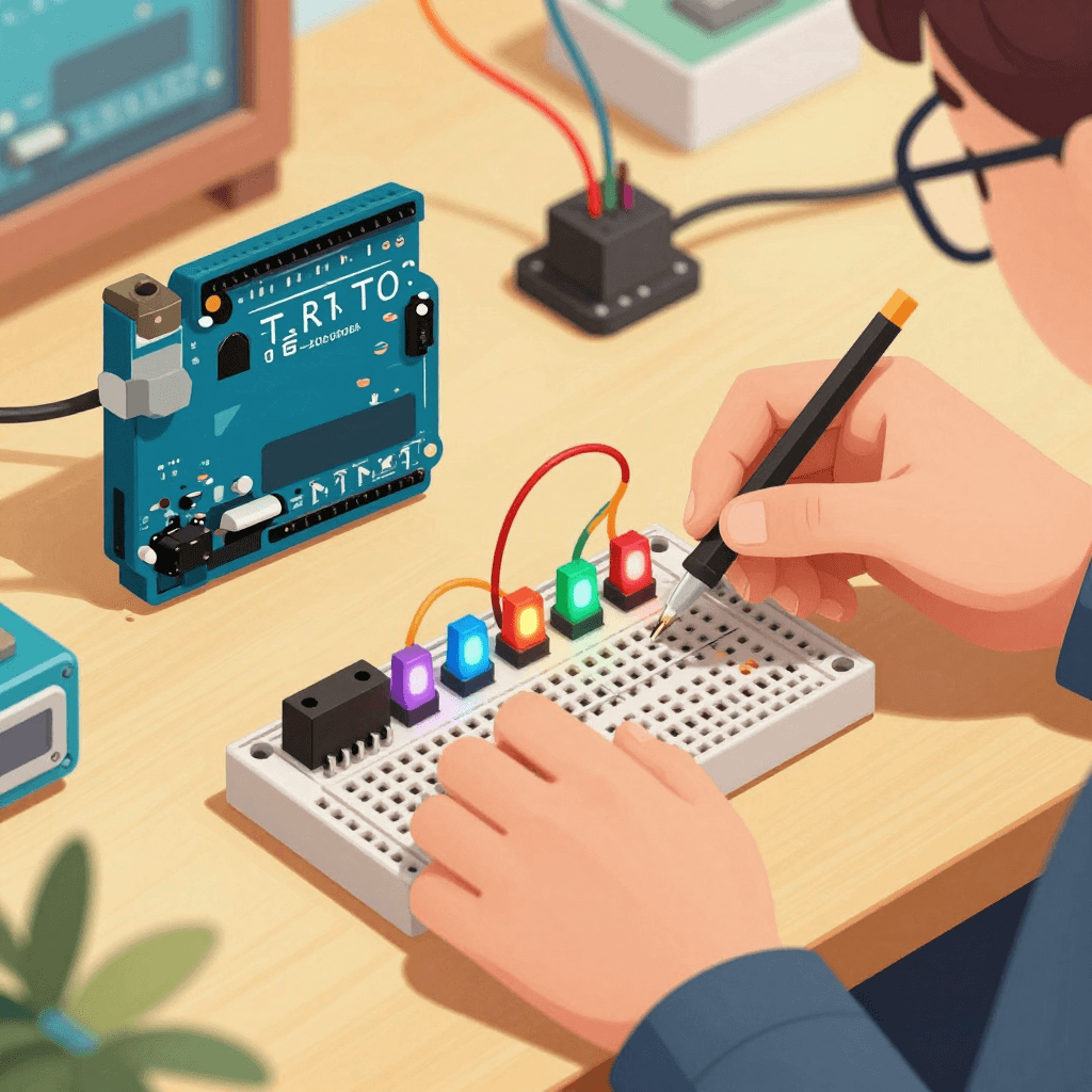
Introduction
We write code every day, but have you ever experienced the moment when that code meets the physical world? The instant an LED lights up in response to your code, a whole new dimension of software development opens up.
This series is an introduction to electronics for software developers. If you know C/C++ or Python, electronics is much easier than you think.
Why Developers Should Learn Electronics
- The True Meaning of Full-Stack — Software + Hardware = Complete System
- The Age of Robotics — Entering the era of humanoid robots in 2026
- IoT/Edge AI — Beyond the cloud, onto devices
- Hobby Becomes Expertise — Embedded developer salaries keep rising
Roadmap
[Stage 1] Arduino Basics (This article)
    └── LED, Buttons, Sensors, Servo Motors
[Stage 2] ESP32 IoT
    └── WiFi, MQTT, Web Dashboard
[Stage 3] Raspberry Pi + Camera
    └── Computer Vision, Edge AI
[Stage 4] ROS 2 Robotics
    └── Autonomous Driving, Manipulators
[Stage 5] AI + Hardware Fusion
    └── Voice-Controlled Robot, Smart Home
What You Need (Under $40 is enough!)
| Component | Price | Purpose |
|---|---|---|
| Arduino Uno R4 WiFi | ~$19 | Main board |
| Breadboard + Jumpers | ~$4 | Circuit wiring |
| 37-in-1 Sensor Kit | ~$11 | Various exercises |
| SG90 Servo Motor x2 | ~$3 | Motor control |
Fundamental Concepts: Just 3 Things
1. Digital vs Analog
Digital: 0 or 1 (ON/OFF)
  → LED control, button reading
  → Arduino: digitalRead(), digitalWrite()

Analog: Continuous values 0~1023
  → Temperature sensor, light sensor
  → Arduino: analogRead(), analogWrite() (PWM)
2. Voltage, Current, Resistance (Ohm's Law)
V = I × R

V (Voltage) = 5V (Arduino default)
R (Resistance) = 220Ω (LED protection)
I (Current) = 5V / 220Ω = 22.7mA ✅ (Safe range for LED)
Developer Analogy: Voltage = API request, Current = Data flow, Resistance = Rate Limiter
3. GPIO (General Purpose Input/Output)
Arduino Uno R4:
  Digital Pins: D0~D13 (Input/Output)
  Analog Pins: A0~A5 (Input)
  PWM Pins: D3, D5, D6, D9, D10, D11 (Pseudo-analog output)
  Power: 5V, 3.3V, GND
Exercise 1: Blinking an LED (Hello World)
Circuit
Arduino D13 ──[220Ω]──[LED(+)]──[LED(-)]── GND
Code
// Blink — The Hello World of Electronics
void setup() {
    pinMode(13, OUTPUT);  // Set D13 as output
}

void loop() {
    digitalWrite(13, HIGH);  // LED ON
    delay(1000);             // Wait 1 second
    digitalWrite(13, LOW);   // LED OFF
    delay(1000);             // Wait 1 second
}
Python developer? You can use MicroPython instead of Arduino IDE!
# MicroPython (runs on ESP32)
from machine import Pin
import time

led = Pin(13, Pin.OUT)

while True:
    led.value(1)   # ON
    time.sleep(1)
    led.value(0)   # OFF
    time.sleep(1)
Exercise 2: Control LED with a Button
const int buttonPin = 2;
const int ledPin = 13;
int buttonState = 0;

void setup() {
    pinMode(ledPin, OUTPUT);
    pinMode(buttonPin, INPUT_PULLUP);  // Use internal pull-up resistor
}

void loop() {
    buttonState = digitalRead(buttonPin);

    if (buttonState == LOW) {  // Button pressed (LOW because of PULLUP)
        digitalWrite(ledPin, HIGH);
    } else {
        digitalWrite(ledPin, LOW);
    }
}
Exercise 3: Temperature & Humidity Sensor (DHT11)
#include <DHT.h>

#define DHTPIN 2
#define DHTTYPE DHT11

DHT dht(DHTPIN, DHTTYPE);

void setup() {
    Serial.begin(9600);
    dht.begin();
}

void loop() {
    float humidity = dht.readHumidity();
    float temperature = dht.readTemperature();

    Serial.print("Temperature: ");
    Serial.print(temperature);
    Serial.print("°C / Humidity: ");
    Serial.print(humidity);
    Serial.println("%");

    delay(2000);
}
Exercise 4: Servo Motor Control (The Start of a Table Tennis Robot!)
#include <Servo.h>

Servo myServo;

void setup() {
    myServo.attach(9);  // Connect servo to D9
}

void loop() {
    // Sweep 0° → 180°
    for (int angle = 0; angle <= 180; angle += 10) {
        myServo.write(angle);
        delay(50);
    }
    // Sweep 180° → 0°
    for (int angle = 180; angle >= 0; angle -= 10) {
        myServo.write(angle);
        delay(50);
    }
}
Exercise 5: LED Brightness Control with PWM
const int ledPin = 9;  // PWM pin

void setup() {
    pinMode(ledPin, OUTPUT);
}

void loop() {
    // Fade in
    for (int brightness = 0; brightness <= 255; brightness += 5) {
        analogWrite(ledPin, brightness);
        delay(30);
    }
    // Fade out
    for (int brightness = 255; brightness >= 0; brightness -= 5) {
        analogWrite(ledPin, brightness);
        delay(30);
    }
}
Developer Project Ideas
| Project | Difficulty | Software Integration |
|---|---|---|
| Table Tennis Scoreboard | ⭐⭐ | fingerscore integration |
| Server Room Temp Monitor | ⭐⭐ | Grafana Dashboard |
| Intrusion Detection Alert | ⭐⭐⭐ | Telegram Bot notification |
| 2-Axis Camera Pan-Tilt | ⭐⭐⭐ | OpenCV face tracking |
| Custom Macro Keyboard | ⭐⭐⭐ | Dev productivity tool |
| AI Smart Home | ⭐⭐⭐⭐ | K8s + MQTT + LLM |
AI + Electronics Fusion (Ultimate Goal)
[Arduino Sensors] → [ESP32 WiFi] → [K8s MQTT Broker]
                                        ↓
                               [AI Inference (GPU Server)]
                                        ↓
                               [Control Commands → Motors/LEDs]
Connecting your home GPU servers with Arduino enables:
- Voice command → Qwen3-TTS → Speaker (omen)
- Camera feed → LTX-2 analysis → Servo motor control (spark01)
- Sensor data → Anomaly detection AI → Alerts (spark02)
Series Roadmap
| Part | Topic | Status |
|---|---|---|
| 1 | Arduino Basics (This article) | ✅ |
| 2 | ESP32 WiFi + MQTT IoT | 🔜 |
| 3 | Raspberry Pi + Camera Vision | 🔜 |
| 4 | ROS 2 Robot Control Basics | 🔜 |
| 5 | AI + Hardware Integration Project | 🔜 |
Quiz — Electronics Fundamentals (Click to check!)
Q1. If you connect a 1kΩ resistor to a 5V power supply using Ohm's law V = I x R, what is the current? ||5V / 1000Ω = 5mA (0.005A)||
Q2. What is the difference between digital and analog pins on Arduino? ||Digital: Only two states — 0/1 (HIGH/LOW). Analog: Can read continuous values in the range 0~1023 (10-bit ADC)||
Q3. What is PWM (Pulse Width Modulation) and what is it used for? ||A technique that adjusts the ON/OFF ratio (duty cycle) of a digital signal to create pseudo-analog output. Used for LED brightness control and motor speed control||
Q4. What value is read when a button is pressed in INPUT_PULLUP mode? ||LOW (0) — The internal pull-up resistor keeps the pin HIGH normally, and pressing the button connects it to GND resulting in LOW||
Q5. What is the measurement range and accuracy of the DHT11 sensor? ||Temperature: 050°C (±2°C), Humidity: 2080% (±5%). Low precision for the price, but sufficient for beginners||
Q6. What is the control signal and operating range of the SG90 servo motor? ||PWM signal (50Hz, 12ms pulse width), 0180 degree rotation. Uses the Servo library, not analogWrite||